
History of propellers: from the water screw to the modern propeller
The history of propellers starts with the screw: the first marine propellers were long screws, and it was by keeping only fractions of a pitch, around 1840, that the modern propeller took its present shape of separate blades. It took a few millennia to get there. The path runs through the water lift, the windmill, Leonardo da Vinci's drawings and the balloons of the 18th century. It ends in a simple physical idea, which we come back to at the bottom of this page: to push efficiently, you must move a lot of fluid at low speed.
In this page:
- Nature had already found it
- The Archimedes screw, the first propeller
- History of the windmill and the wind turbine
- Leonardo da Vinci and the propeller
- Aircraft propellers: from balloons to aviation
- Boat propellers: from the screw to the marine propeller
- Propeller efficiency: why a large propeller beats a small one
1: Nature had already found it
What could be simpler than the propeller? It seems that man only had to copy from nature a shape already suited to what he expected of it. The maple samara, that single-winged seed that spins as it falls, already does this job.
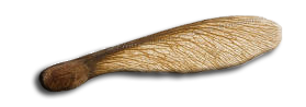
The maple samara: the seed acts as a counterweight, and the ribbed wing starts to spin as it falls.
Yet man did not get there by copying. It took millennia to reach this deceptive simplicity. Its ancestors are the wing, the paddle wheel, the oar and the windmill, each in a great variety of forms.
2: The Archimedes screw, the first propeller
According to tradition, the ancient Chinese civilization was the first to use the propeller, as a water lift. Traces of such a lift have also been found on the banks of the Nile. Several centuries before the Christian era, people there used the "Egyptian snail", which we can see as a propeller that moves a fluid.
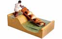
A water screw as a model: as it turns, the helical screw lifts what it holds along the slope.
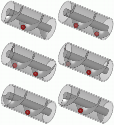
The principle of the Archimedes screw: the ball is trapped between the helical thread and the tube. When the screw turns, the ball moves along the axis.
It is said that Archytas (-428/-360), a disciple of Pythagoras, renewed this invention. Archimedes (-287/-212) is then said to have used it for a different purpose, as a screw conveyor. In this form, the "Archimedes screw" is still used in some plants, for example to remove machining chips.
3: History of the windmill and the wind turbine
The conquest of wind energy does not date from yesterday. The need to turn wind energy into mechanical energy led to the invention of the propeller that captures the energy of a fluid. Windmills existed from the earliest antiquity, in Persia, Iraq, Egypt and China. Hammurabi, king of Babylon, is said to have planned, seventeen centuries before Christ, to irrigate the plain of Mesopotamia with wind energy. The mills of that region were probably vertical-axis machines, like those whose ruins remain on the Iranian plateau.
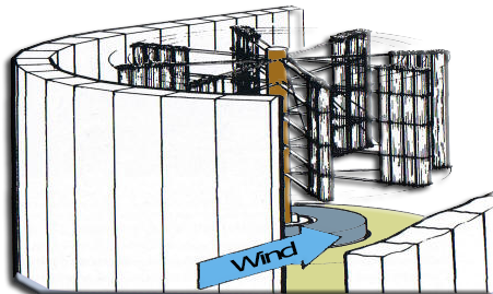
A panemone, a simple drag-type wind machine used in Persia to grind grain: the surrounding wall directs the wind onto the blades on one side only.
Heron of Alexandria (10/70), an Egyptian Greek, describes in his study on pneumatics a horizontal-axis mill that feeds compressed air to an organ.
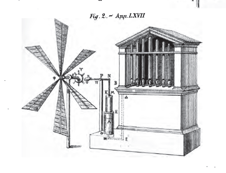
Heron's wind-driven organ: on the left, the wings of the mill; on the right, the pump and the organ they supply.
The translation quoted by the source of this page describes how the machine works:
"…the second has wings like those of windmills. When these wings, driven by the wind, turn the disc Φ, the bar also turns, driving the disc Υ and its cams, which strike the pallet and lift the piston… The frame that supports the bar can be moved so as to always take advantage of the prevailing wind, and so produce a faster and more continuous rotation…"
The Greeks of Alexandria therefore knew the windmill. The Romans seem to have used it very little: Vitruvius and Varro only speak of water mills. Was the windmill widespread in Egypt? It is hard to say. We can, however, place the birthplace of wind engines in the eastern Mediterranean basin and in China, where only vertical-axis machines were known.
Windmills appear in Europe only in the Middle Ages, first in Italy, France, Spain and Portugal, then in Great Britain, Holland and Germany. Some authors credit the Crusaders returning from the Middle East with introducing them. Viollet-le-Duc reports that in Normandy, in the 14th century, they were called "Turkish mills", in memory of that origin. It is not impossible.
These horizontal-axis machines carry four wings in a cross. They mainly grind grain. Holland uses them from 1350 to drain polders, coupled to bucket wheels or Archimedes screws that lift water up to five meters. They are also used to press oil from nuts and seeds, saw wood, turn rags into paper, prepare the colored powders of dyes, and make snuff, which people took before they had cigarettes.
4: Leonardo da Vinci and the propeller
The propeller reappears only with Leonardo da Vinci (1452/1519). Leonardo studies the different ways to lift water, among them the screw.
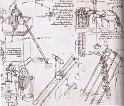
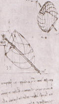
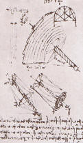
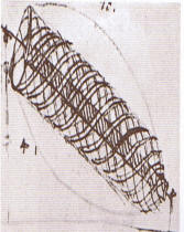
Pages from Leonardo's notebooks on lifting water: machines, then different outlines of screws.
He is said to have been the first to state that a propeller set in motion in air or water must move along its axis. This is his famous drawing of a helicopter, which presents the propeller as a means of propulsion for a vehicle.
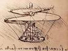
Leonardo's "aerial screw": a helical surface meant to screw itself into the air.
Another, lesser-known drawing is just as instructive about the use of the propeller to capture the energy of a fluid. Here, the stream of hot air rising in a column above a heat source is turned into mechanical energy. Some solar power plant projects use this process today. The shape of the propeller is astonishingly modern.
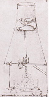
Hot air rises in the column and spins the propeller placed in the duct, and a gear passes this motion on to the mechanism.
5: Aircraft propellers: from balloons to aviation
After Leonardo, the Englishman Hooke proposed in 1681, for ship propulsion, wings similar to those of windmills. At the time, boats moved only by paddle wheels. The mathematician Bernoulli took up this idea in 1752, and James Watt made a similar proposal in 1784. But the time of the propeller had not yet come: the machines on board did not exceed a few dozen horsepower, so paddle wheels were not yet too bulky.
The first use of the propeller, as a hydraulic motor driving mills, dates back to 1699. It is due, it seems, to the French mechanic Duquet, and a second, identical one to the mechanic Dubost in 1743. The Frenchman Paucton then thought of applying the aircraft propeller to air propulsion. In his "Theory of the Archimedes screw", published in 1768, he describes a helicopter with two "pterophores" (wings): one with a vertical axis to climb, the other with a horizontal axis to advance and steer. At the time, propulsion and steering were not yet told apart.
The first first propeller applied to a full-scale flying machine is due to the Frenchman Blanchard, in 1784 (fig. 1). He fitted a balloon with one, without much result in either propulsion or steering.
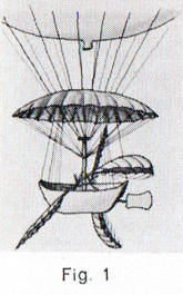
Blanchard's balloon, 1784 (fig. 1).
From this trial, we should not conclude that the propeller was adopted at once and that the following years were spent perfecting it alone. After 1784, people still tried to move balloons with various systems of oars. Bredin's airship project, the same year, called for paddle wheels. Note how the blade pivots as it comes back up (fig. 2).
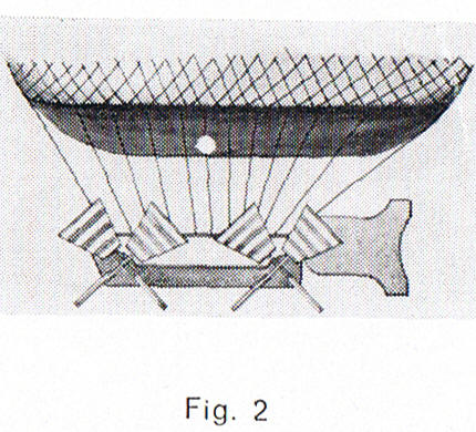
Bredin's project, 1784 (fig. 2): paddle wheels whose blades pivot on the way up.
Then came, in 1785, the balloon of Alban and Valet (fig. 3), driven by a sort of large propeller, with vertical movement through oars with flaps, and that of Guyton de Morveau (fig. 4), driven by oars. In 1860, a propeller with "undulating surfaces" equipped Gontier-Grigny's balloon (fig. 5).
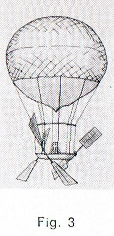
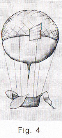
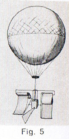
From left to right: the balloons of Alban and Valet (1785), Guyton de Morveau (1785) and Gontier-Grigny (1860). None carries the propeller as we know it.
The same year as Blanchard, two other Frenchmen, Launoy and Bienvenu, tried "contra-rotating" propellers on their model helicopter. The propeller caught on fairly quickly in ballooning, faster than in marine propulsion, and heavier-than-air craft knew no other propulsor until jet reaction. But the propeller of that time lacked today's simplicity: it sometimes resembled a paddle wheel, a paddle, an oar or a fan.
6: Boat propellers: from the screw to the marine propeller
How did we go from the Egyptian snail to the boat propeller? The propeller we know descends from the screw: it was meant to screw itself into the water like a bolt into a nut. By analogy, the first marine propellers were very long, and their axis, which was none other than the engine shaft, carried several "pitches", several "threads". How did we go from this form to the present one, with a fraction of a pitch? Chance decided, as in many discoveries.
The story goes that in 1836, one of the first boats fitted with a propeller, an English vessel, broke it. There it lay, immobilized. It tried to set off again with the part of the "screw" that remained and, curiously, its speed had increased. The English were left astonished and deduced nothing. The Frenchman Augustin Normand, however, drew major conclusions from it, as we shall see.
Let us go back to our "water screw", at the time of Duquet and Dubost. In 1768, Paucton stated that the Archimedes screw could propel ships, but nothing was built. Then came the patents of the Englishman Bramah (1785), the Americans Lyttelton (1794) and Shorter (1799), the Frenchman Dallery (1803), the American Stevens (1804) and Rennie (1820, fig. 6). Delisle (1823, fig. 7), Bourdon (1824), the Austrian Ressel (1826), Cummerow (1829), Smith (fig. 8), Woodcroft (1832) and the Frenchman Frédéric Sauvage (1832, fig. 9) followed.
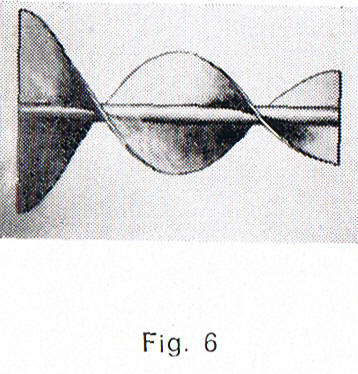
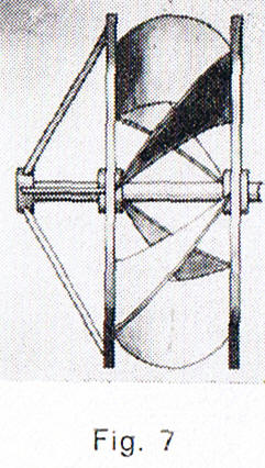
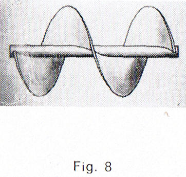
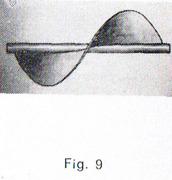
Screw-type propellers, figures 6 to 9. Sauvage's, bottom right, has only a single thread around the shaft.
Sauvage's contribution is crucial for two reasons. First, he was the first to propose a propeller with a single thread, rather than a screw on a long shaft. Second, he made several attempts, all successful. If they did not see the development they deserved, it is because the official authorities understood nothing of them. The Swedish engineer Ericsson had to develop a similar propulsor, in 1836, for it to spread in England and America. France then understood that Sauvage's propeller was far superior to paddle wheels.
The story of Sauvage's propeller is worth telling. Frédéric Sauvage thought the paddle wheel system poor and looked for another solution. He found it watching a goldfish swim in its bowl: "That is the propulsor we need, he said. It is the sculling motion of the fish's tail, which constantly pushes against the liquid; this sinuous movement is comparable to that of a screw advancing in water." The same goes for the movement of the feet in the crawl stroke, given the position they must have.
How could the action of the fish's tail be translated mechanically? On a cylindrical piece of wood as thick as a pencil, Sauvage drew a line in the shape of a geometric helix. Along that line, perpendicular to the axis, he drove needles very close to each other. This gave the structure of a helical surface, which he finished by gluing oiled cloth onto the needles. Such was his first propeller. Mounted on a 27 cm model boat, it was a success, driven by a counterweight and pulley system. Sauvage then made a copper propeller, driven by a counterweight and clockwork. Then he mounted two propellers side by side, turning in opposite directions to balance the boat. A patent was granted to him on May 28, 1832.
But the invention of the propeller ran against powerful interests tied to paddle wheels. Much like today with fossil fuels… For several years, Sauvage fitted his propellers to boats moved by human arms, unable to find the support needed to fit them to steamboats. The opportunity came in 1841 from a boat builder of Le Havre, Augustin Normand. The two men became close, then parted on one precise point: the fraction of pitch, which Sauvage opposed. This is where Augustin Normand's contribution lies.
Normand started from both the mishap of the English ship and Sauvage's single-thread propeller. He thought it worthwhile to split the whole thread (fig. 10), so that the new propulsor would carry only "fractions of a pitch" taken at regular intervals on the thread corresponding to one turn. The propulsive surface was thus spread over several blades. The navy then had the multi-bladed propeller it uses today.
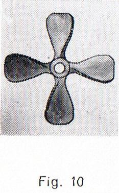
On the left, Sauvage's propeller (screw type); on the right, Augustin Normand's fractioned propeller (reaction type), here with four blades.
This is a major advance in the design of the propulsor. It moves the propeller from the stage of a screw to that of a "reaction" propulsor, in line with Newton's principles (F = m × a) and action-reaction. From this revolution, which the 1836 ship anecdote presents as accidental, descend our modern propeller and its calculation method.
7: Propeller efficiency: why a large propeller beats a small one
To understand the gain in efficiency and the assumption behind performance calculation, let us state the general problem of the propulsor. Thrust (newtons) is the product of two factors: a mass flow rate and a change of speed. It is the change of momentum of the fluid that generates thrust.
Thrust = mass flow rate × (speed downstream of the propeller − speed upstream of the propeller)
- The mass flow rate (kg/s) is the mass of fluid moved in one second.
- The change of speed (m/s) is the difference between the fluid speed behind the propeller and its speed in front of it.
- The power needed to produce this thrust is thrust (N) × speed (m/s).
To measure the quality of the propulsor, we must tell apart two powers at play. The useful power is the one that serves the motion: thrust × speed upstream of the propeller. The kinetic power is the one the propeller gives to the fluid, computed from the change in kinetic energy of the fluid (kinetic energy = 0.5 × mass × speed2).
Kinetic power = 0.5 × mass flow rate × (speed downstream2 − speed upstream2)
Imagine a boat tied to the quay, or an aircraft with its brakes on before takeoff, whose propeller turns and produces thrust. The vehicle is stationary: its speed is zero, so the useful power is too. Yet the thrust is real, and the engine burns energy. That energy is wasted, and we must quantify it: this is the role of the kinetic power. A good propeller, one that earns money by carrying goods with a minimum of energy, gives the maximum useful power for the minimum kinetic power.
Propeller efficiency = useful power / kinetic power
Replacing the thrust by its expression shows the role of the speeds:
- Useful power = mass flow rate × (speed downstream − speed upstream) × speed upstream;
- Kinetic power = 0.5 × mass flow rate × (speed downstream2 − speed upstream2).
The useful power is proportional to the change of speed. The kinetic power grows faster with that change, because the speed downstream enters it squared. To push without waste, we must therefore change the fluid speed as little as possible. Since thrust is the product of the mass flow rate and the change of speed, it is better to raise the flow rate than the change of speed. A flow rate is a speed multiplied by a cross-section: to raise it without changing the speed, we must enlarge the propeller diameter. The larger the propeller, the less it needs to change the fluid speed to create thrust, and the better its propulsive efficiency.
This principle holds today as it did a thousand years ago: for high efficiency, we need a high flow at a speed as low as possible. But it took millennia of reflection to establish that the propeller shape was the one that most simply pushed back an enormous mass of fluid at low speed.
Bibliography
- Jean Grampaix, Histoire de l'hélice (in French), éditions d'Argenson, 1966.
- Léonard de Vinci (in French), éditions Atlas, 1986.
- Paul Gipe, Le grand livre de l'éolien (in French), éditions du Moniteur, 2004.
- Website: Heron of Alexandria's Pneumatics (in French).
To go further, we can see how the evolution of calculation methods followed that of the propeller, or put numbers on the effect described above with the propulsive propeller at zero speed, and come back to the notion of propeller pitch.
 Global site map
 Mecaflux
 Tutorials Mecaflux Pro3D
 Tutorials Heliciel
 Tutorials Heliciel PRO CFD
 Mecaflux Store
 Compare software functions
 Quotes, Orders, Payment Methods
 project technical studies