
Multiple operating point analysis of a propeller, wind turbine, tidal turbine or fan: off-design curves
The multiple operating point analysis plots the performance of a propeller, wind turbine, tidal turbine or fan over a whole range of speeds, for a given blade geometry. You choose the quantity that varies (the rotation speed or the fluid speed) and the range to test; Heliciel calculates the series of operating points requested (ten by default), plots the curves and gives you the table of values. It is the tool that answers the question: "what becomes of my propeller when it does not turn at its design speed?"
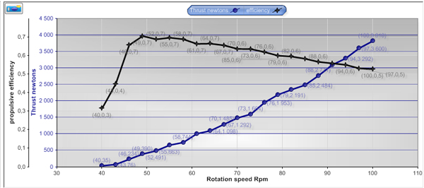
A multiple analysis result: thrust and propulsive efficiency as a function of rotation speed.
In this page:
- Operating point and design twist
- Off-design calculation and multiple analysis
- Using the multiple analysis, step by step
- Reading the results: the negative efficiency example
- Real rotation speed with a motor or a generator
- Limits to check: strength and cavitation
1: Operating point and design twist
Optimizing a propeller involves analysing its performance at the different operating points. The operating point of a propeller, whether it captures energy from the fluid or propels, is defined by two quantities: the rotation speed and the speed of the fluid (or of the vehicle). The propeller must of course be created with a twist that matches a nominal operating point.
- The fluid speed is, for a boat, the cruising speed; for a wind turbine, the wind speed most often met; for a fan, the speed that gives the flow rate you want.
- The rotation speed is the one at which the motor or generator gives its best efficiency. If that is not possible, a gearing can be used.
Heliciel creates the twist suited to the operating point: just use the "build optimum twist" function.

2: Off-design calculation and multiple analysis
In reality, a propeller does not always run at its nominal operating point, the "design" point. It must therefore be possible to determine its performance when it leaves it. Heliciel lets you change the rotation speed or the fluid speed and test the performance while keeping the twist: you are then in "off-design" mode.
Calculate off-design performance.
The multiple analysis repeats this off-design calculation at many points, plots the curves and collects the performance of a fixed propeller geometry. This geometry can come from the function Rebuild the optimum twist, or have been defined in reverse engineering mode (modelling an existing propeller).
3: Using the multiple analysis, step by step
Open the interface. Click Multi Analysis in the Heliciel toolbar:
The Multi Analysis button in the toolbar.
You can also use the Multi Analysis button under the 3: Optimize tab.
Choose the varying parameter. An operating point is defined by the fluid speed and the rotation speed. The parameters that vary in the analysis are therefore these two quantities: you choose one of them, and the other stays constant.
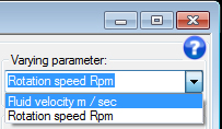
Selecting the varying parameter.
Set the test range. The varying parameter is tested within the range you set. This range is divided into a number of test points that you set (from 5 to 25, ten by default), spaced by an increment that the window shows. When the rotation speed varies, the window also shows the advance ratio J = V0/(n·D) (fluid speed divided by the product of the rotation speed in revolutions per second and the diameter) at both ends of the range.
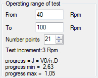
A range from 40 to 100 rpm with 21 test points, 3 rpm apart.
Choose the type of analysis. Two methods of calculating the operating points are offered:
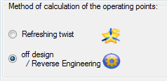
- "Refreshing twist": the optimum twist is adapted to each operating point tested. Heliciel updates the twist and calculates the performance of the propeller at each point. You thus check the optimum performance that your propeller gives, for the blade dimensions chosen.
- "Off design / Reverse Engineering": the twist and the pitch angle of the propeller stay constant, and the propeller is analysed in off-design mode. You thus see how the performance of a given propeller changes away from its design point.
All that remains is to start the analysis. The graphs can be saved; a "Compare" graph shows the curves of your choice; the calculation data can be saved as text or spreadsheet. A list of displayed curves lets you choose what you plot: thrust, torque, shaft power, useful power, thrust and power coefficients, propulsive efficiency, pressure difference, and other flow quantities.
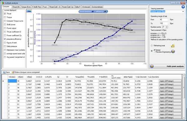
The multiple analysis window: the curves in the centre, the settings on the right and the table of test points at the bottom.
4: Reading the results: the negative efficiency example
The test range you choose can give results that fall completely outside the propeller's way of working, and give negative efficiencies, for example. In the example below, the range of rotation speeds tested for a propulsive propeller shows an efficiency that is negative below about 75 rpm, then positive from 80 rpm on, and about 0.2 around 110 rpm. In the negative zone, the propeller works as an energy capture device: the fluid turns it instead of it accelerating the fluid. For that range of operation, a capture propeller would be more efficient.
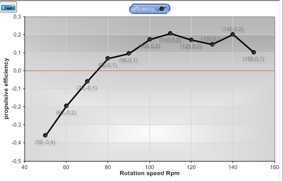
The propulsive efficiency as a function of rotation speed: negative from 50 to 75 rpm, positive above.
5: Real rotation speed with a motor or a generator
Finding the real rotation speed (operating point) for electric motors and generators coupled to propellers.
- The rotation speed of an electric motor depends on the resisting torque applied to it. The real operating speed of a motor is the speed given by the intersection of the motor torque curve and the resisting torque curve of the propeller.
- For a wind-turbine type generator driven by a capture propeller, the problem is the same: you must find the speed at the intersection between the resisting torque curve of the generator and the torque curve of the propeller.
In both cases, the real rotation speed of the system is set by the balance between the resisting torques and the driving torques. To see quickly the rotation speed of your generator-propeller or electric motor-propeller set, just superimpose the torque curve of the propeller and the torque curve of the motor or generator. To make this graphical solution easier, you can enter your own torque curve, supplied by the manufacturer of the motor or generator, and show it superimposed. In the Compare tab of the multiple analysis window, the Enter a torque curve compared button opens the entry form.
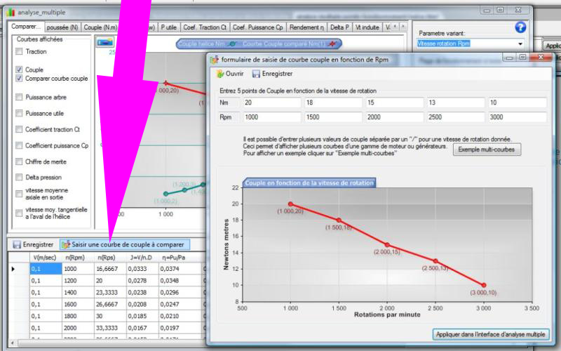
Entering the torque curve: five torque points (in N·m) as a function of rotation speed (in rpm).
You can also enter several torque curves, to represent a range of motors or generators (three curves in the example below), and edit performance curves as a function of rotation speed. You see directly the rotation speeds and the performance of the same propeller mounted on motors of different powers.
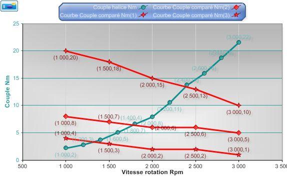
The propeller torque (rising curve) grows with rotation speed; each motor curve (falling or nearly flat curves) crosses it at a point, which gives the real rotation speed.
Here we find that:
- the propeller mounted on the weakest motor (torque curve of 4 N·m at 1,000 rpm) will run at about 1,300 rpm;
- the propeller mounted on the intermediate motor (curve of 8 N·m at 1,000 rpm) will run at about 1,750 rpm;
- the propeller mounted on the most powerful motor (curve of 20 N·m at 1,000 rpm) will run at about 2,400 rpm.
We can also superimpose the power and thrust data to know the performance of the system in the three cases:
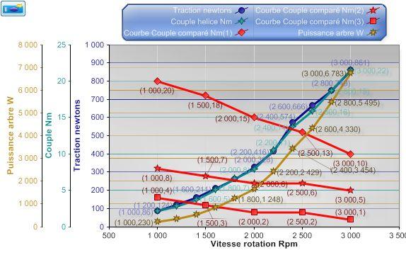
Thrust, shaft power and torque superimposed: at each rotation speed found, we read the thrust and the power.
- With the weakest motor: about 150 N of thrust at 1,300 rpm, for a shaft power of about 300 W.
- With the intermediate motor: about 250 N at 1,750 rpm, for about 1,200 W.
- With the most powerful motor: about 550 N at 2,400 rpm, for about 3,400 W.
6: Limits to check: strength and cavitation
Of course, these values are valid only if the propeller has a mechanical strength suited to the calculated thrust, and if cavitation does not vaporize the fluid. You must therefore check these parameters at the rotation speeds found!
To go further, we can model an existing propeller with the page on reverse engineering an existing propeller, then follow its performance over the range of speeds you are interested in.
 Global site map
 Mecaflux
 Tutorials Mecaflux Pro3D
 Tutorials Heliciel
 Tutorials Heliciel PRO CFD
 Mecaflux Store
 Compare software functions
 Quotes, Orders, Payment Methods
 project technical studies