
Froude theory and the Betz limit: wind turbines, tidal turbines and energy-capturing rotors
Froude theory and the Betz limit describe how much power a wind turbine or tidal turbine can capture: the theory treats the energy-capturing rotor as a disc that slows the fluid, links the axial induced velocity to thrust and power, and leads to the Betz limit, 16/27 or 59.3% of the power of the fluid crossing the disc. This page works through the reasoning step by step, with all its formulas. It rests on the momentum balance, which is worth having in mind before you start.
In this page:
- Assumptions of Froude theory
- Momentum balance
- Pressure, velocity at the disc and induced velocity
- Extracted power, power coefficient Cp and the Betz limit
- Worked example: a 10 m diameter wind turbine
- Limits of Froude theory
1: Assumptions of Froude theory and the actuator disc
Froude's method uses the momentum conservation equations to compute the performance of a propeller or rotor. It treats the rotor as a uniformly loaded disc with an infinite number of blades. The axial induced velocities follow from it. The assumptions are:
- the rotation of the flow is neglected;
- the fluid is incompressible;
- the flow outside the stream tube crossing the disc is undisturbed;
- the pressure far upstream and far downstream equals the static pressure of the undisturbed flow;
- the fluid crosses the rotor without friction.
The disc acts as a brake: it opposes a force T to the fluid stream. We can see it as the result of the pressure difference between the upstream and downstream sides of the disc.
The continuity equation tells us that to keep the same flow rate, the cross-section must grow when the velocity drops. The stream tube crossing the disc therefore widens, since the disc slows it down. Let us watch the rotor in a control volume larger than this tube: the widening is only possible if part of the fluid leaves the control volume through its sides.

Figure 1: the stream tube widens as it crosses the disc; the lower curves show velocity and pressure along the axis. The labels in this figure are hard to read at this size.
2: Momentum balance of a wind turbine or tidal turbine
We write V0 for the velocity far upstream, V1 for the velocity at the disc, V2 for the velocity far downstream, r for the radius of the stream tube far downstream and R for the radius of the control volume. For an energy-capturing rotor, V2 is lower than V0.
The continuity equation gives the volume leaving the control volume per second, that is the volume flow rate Q in m3/s:
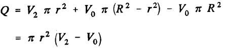
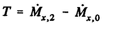
The sign of Q reflects a physical fact: since V2 is lower than V0, Q is negative, and fluid leaves the control volume sideways. The momentum theorem then gives the axial force T, that is the change of momentum between sections 2 and 0, projected on the rotor axis:
The time derivative of the momentum is:
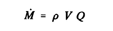
The momentum M2 leaving the control volume at section 2 is:

The total momentum M1 entering the control volume is the momentum at the volume inlet, minus the momentum evacuated through the sides:

Reading note: since V2 is lower than V0, the momentum evacuated sideways is ρ(V0 − V2)πr²V0. The image above writes this term with (V2 − V0) preceded by a minus sign; it must be read with the sign that gives the formula for T below, that is M1 = ρπR²V02 + ρ(V2 − V0)πr²V0.
The axial force (T = M2 − M1) then becomes, with the simplification on the second line:

This force is computed on the fluid side: for a brake it is negative, and the force the fluid exerts on the rotor is its opposite.
3: Pressure, velocity at the disc and induced velocity
The same force can be written with the static pressure acting on the disc:
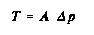
where A is the area of the disc swept by the rotor and Δp the pressure difference across the disc. The Bernoulli equation reads, from 0 to 1 upstream:
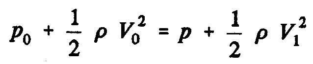
and from 2 to 1 downstream:
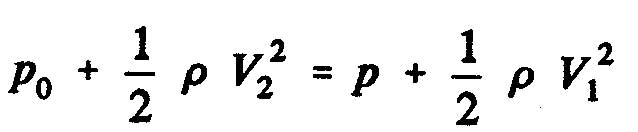
The static pressure difference between the downstream and upstream faces of the disc is therefore:

The continuity equation between the disc and section 2 reads 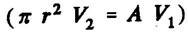 , which allows us to write:

We conclude that the flow velocity at the disc is the arithmetic mean of the upstream and downstream velocities:
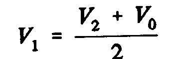
The induced velocity, written w, is the change of velocity at the disc, and a is the axial interference factor:
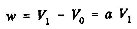

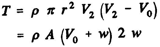
Reading note: these two images mix two conventions. For an energy-capturing rotor, the induced velocity is a slowing down, which we define as w = V0 − V1 = a V0. The factor a is then the fraction of velocity lost at the disc, the definition used in the rest of the page.
With the mean , the axial force acting on the disc becomes:
4: Extracted power, power coefficient Cp and the Betz limit formula
From here on, we write V for the velocity at the disc (written V1 above) and V1 for the velocity far downstream (written V2 above), as in the images that follow. The power extracted from the fluid is:

The power coefficient Cp is the ratio of the extracted power to the power available in the fluid:

The axial interference factor a is the fraction of velocity lost between the free stream upstream of the rotor and the rotor plane:
V = (1 − a) V0
Using the velocity mean (), we obtain the velocity far downstream:
V1 = (1 − 2a) V0
Knowing that the force can also be written as a pressure difference across the disc:

Substituting V1 and V, we obtain the thrust and the power:

The expression of Cp becomes:

The theoretical maximum of Cp, the Betz limit, is found where the derivative of Cp with respect to a vanishes:

Reading note: differentiating Cp = 4a(1 − a)2 gives dCp/da = 4(1 − a)(1 − 3a), not 4(1 − 3a2) as the image states. This derivative vanishes at a = 1/3, the value used by the next result.
This gives:

The maximum efficiency of an ideal wind turbine is therefore about 59.3%. It is never reached in practice, for three reasons:
- the air flow has a rotating component due to the rotation of the rotor;
- drag is never zero, because of friction;
- the rotor has a finite number of blades.
To extract energy, the fluid must slow down as it crosses the rotor. At a = 1/3, the velocity at the disc is two thirds of the upstream velocity, and the velocity far downstream is one third. By continuity, the cross-section of the stream grows from upstream to downstream: for an ideal turbine, the upstream section is two thirds of the rotor area, and the rotor area is half the downstream section. Extracting all the energy of the fluid is impossible; in practice, the efficiency of real wind turbines does not exceed about 45% (an order of magnitude we quote here without recomputing it).
5: Wind turbine worked example, wind power and maximum Betz power
The values below are an example chosen to illustrate the formulas; they are not measurements. Take a wind turbine 10 m in diameter in an 8 m/s wind, with an air density of 1.225 kg/m3.
- The disc area is A = π × 52 ≈ 78.5 m2.
- The power of the wind crossing this disc is ½ ρ A V03 = 0.5 × 1.225 × 78.5 × 83 ≈ 24,630 W, about 24.6 kW.
- The Betz limit caps the recoverable power at 16/27 of this, about 14,600 W (14.6 kW). No turbine of this diameter, however good, can do better in this wind.
At the maximum, a = 1/3. The velocity at the disc is then V = (1 − 1/3) × 8 ≈ 5.33 m/s and the velocity far downstream V1 = (1 − 2/3) × 8 ≈ 2.67 m/s. The thrust on the rotor is T = ½ ρ A V02 × 4a(1 − a) ≈ 2,740 N, and we do recover the power: T × V ≈ 2,737 × 5.33 ≈ 14,600 W. The stream tube section is 2/3 of A upstream (about 52 m2) and 2 A downstream (about 157 m2): the tube widens, as figure 1 shows.
What if the rotor brakes less, say with a = 0.25? Cp = 4 × 0.25 × 0.752 ≈ 0.5625, about 13,850 W: 5% less than the maximum. The Cp curve is flat near its top, which explains why a real rotor can work a little off the optimum without losing much.
6: Limits of Froude theory, drag and wake rotation
This simple one-dimensional model does not describe the rotation of the fluid. It still provides fundamental notions for how wind turbines and tidal turbines work. It gives the axial induced velocity; it says nothing about the shape of the blade.
Three limits are worth keeping in mind. First, there is no drag: the fluid crosses the disc without friction, whereas blade airfoils always have some. Second, the wake does not rotate in the model, whereas the rotor can only extract a torque by making the fluid rotate the other way; the energy of that rotation is lost to extraction. Third, the disc has an infinite number of blades, which erases tip losses. Each of these limits pulls the real Cp below 16/27.
The model also stops being valid when the rotor brakes too much. Beyond a = 0.5, the velocity far downstream would vanish, then reverse, which the assumption of a flow that crosses the disc forbids. Blade element theory handles these heavy brakings with the Glauert correction.
Blade element theory completes the picture. Coupled to Froude's theory, it splits the induced velocity into an axial and a tangential component, which are needed to predict angles of attack and blade geometry.
To go further, we can follow up with blade element momentum theory for energy-capturing rotors, look at the propulsion case in Froude theory for traction propellers, or consult the bibliographic references.
 Global site map
 Mecaflux
 Tutorials Mecaflux Pro3D
 Tutorials Heliciel
 Tutorials Heliciel PRO CFD
 Mecaflux Store
 Compare software functions
 Quotes, Orders, Payment Methods
 project technical studies