
Propeller pitch: from geometric pitch to real pitch
Effective pitch falls short of geometric pitch by the slip. Pitch in millimetres, slip and the efficiency of a Wageningen B-series propeller: propeller pitch calculator
The pitch of a propeller is the distance it would travel in one revolution if it screwed itself into the fluid like a screw into a nut. In water or air, it slips: it travels less, and this real advance is called the effective pitch. The difference between the two, the slip, depends on the propeller's operating point.
On this page:
- The propeller, a screw that slips
- Geometric pitch: a matter of blade angle
- Effective pitch: how far the propeller really travels
- Slip
- A pitch that varies along the blade
- Matching the pitch to the operating point
1: The propeller, a screw that slips
When we turn a screw one revolution in a nut, it advances a fixed distance: its pitch. A propeller works in almost the same way, screwing itself into the fluid.
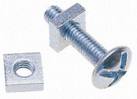
The resemblance is more than a figure of speech: the first marine propellers were true screws, as the history of the propeller tells.
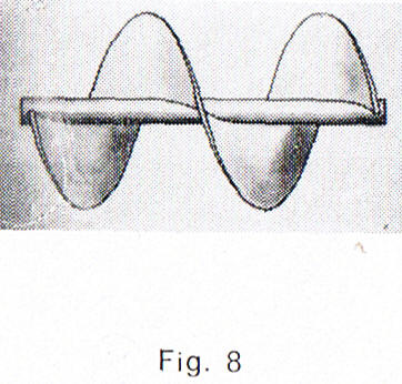
One of the first marine propellers: a screw wound around its shaft.
But a screw bears on a rigid nut, whereas a propeller bears on a fluid that gives way. That is why two pitches must be told apart: the geometric pitch, carried by the blade, and the effective pitch, which the propeller actually travels.
2: Geometric pitch: a matter of blade angle
The geometric pitch is the distance the propeller would travel in one revolution if it were screwed into a nut. It can be read on the blade itself, from the inclination of its sections.
Let us follow a blade section at radius r. In one revolution it travels the circumference 2πr. Its chord is inclined at the pitch angle β to the plane of rotation. If it moved exactly along its chord, it would therefore advance by:
P = 2π r × tan β
where P is the geometric pitch (m), r the radius of the section (m) and β the pitch angle (degrees).
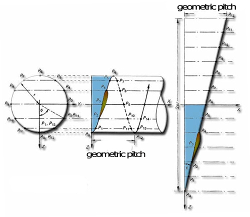
Unrolled onto a plane, the cylinder of radius r becomes a rectangle: the circumference 2πr on one side, the pitch on the other. The path of the section becomes a straight line, inclined at tan-1(P / 2πr).
3: Effective pitch: how far the propeller really travels
In a fluid, a propeller can turn without the boat or aircraft moving, at the bollard or static point for instance. The distance it really travels in one revolution is the distance the vehicle covers during that revolution: this is the effective pitch.
Pe = V / n
where Pe is the effective pitch (m), V the speed of advance of the vehicle (m/s) and n the rotational speed of the propeller (rev/s). Dividing by n amounts to multiplying the speed by the duration of one revolution, 1/n.
Example: a boat moves at 3 m/s and its propeller turns at 5 revolutions per second (300 rpm). One revolution lasts 1/5 = 0.20 s. During that revolution, the boat covers 3 m/s × 0.20 s = 0.60 m: the effective pitch is 0.60 m.
The effective pitch therefore does not depend on the shape of the propeller but on its operating point: the same propeller has zero effective pitch at the static point, and a larger and larger one as the vehicle speeds up at constant rpm.
4: Slip
The geometric pitch therefore does not match the real travel of the propeller. The difference between the two is called slip:
slip = P − Pe and slip ratio = (P − Pe) / P
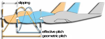
In one revolution the aircraft advances by the effective pitch; it falls short of the geometric pitch by the slip.
Slip is not a flaw: it is because the blade meets the fluid at an angle of attack that it produces thrust. Without slip the geometric angle of attack would be zero, and thrust would come only from the camber of the sections. For a boat, slip follows from the thrust required: the boat propeller pitch and slip calculation gives it for the Wageningen B-series propeller that meets your specification.
5: A pitch that varies along the blade
The circumference 2πr grows from the hub to the blade tip. To keep the same pitch, the blade angle must therefore decrease from root to tip: the blade is twisted.
A constant-pitch blade follows this law exactly. A blade optimised for its operating point departs from it, and its geometric pitch changes along the blade. When "the" pitch of such a propeller is quoted, it is in fact the pitch measured at a reference radius, most often 70 % of the radius (0.7 R).
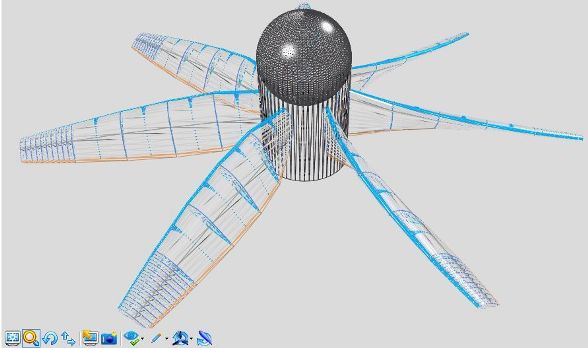
Wireframe view of a propeller in Heliciel: the inclination of the sections changes from hub to blade tips; this is blade twist.
6: Matching the pitch to the operating point
A fixed-pitch propeller is cut for one operating point. When speed or load change a lot (take-off and cruise of an aircraft, a boat light or loaded), it can be useful to change the geometric pitch to suit the effective pitch imposed. That is the role of variable pitch systems.
Heliciel computes the geometric pitch of each blade element with the formula P = 2π r × tan β, from the blade angle chosen by the design. For an existing propeller, the reverse-engineering mode starts from the measured geometry and computes its performance: rebuild a propeller.
To go further, we can see how blade twist and pitch angle are computed element by element, or how the operating point of a propeller sets the angle of attack of each of its sections.
 Global site map
 Mecaflux
 Tutorials Mecaflux Pro3D
 Tutorials Heliciel
 Tutorials Heliciel PRO CFD
 Mecaflux Store
 Compare software functions
 Quotes, Orders, Payment Methods
 project technical studies