
Resistance to forward motion of a boat hull: components, Froude number and calculation
The resistance to forward motion of a boat hull is the force, in newtons, that opposes its course: the propeller must deliver an equal thrust to hold the target speed. We split it into viscous resistance, wave resistance and aerodynamic resistance. The Froude number, Fn = V/√(g·Lf), tells us which one dominates, depending on whether the ship plods along, sails in its own wave, or planes.

Ripples on a stretch of water: a hull draws a whole system of them, and each crest carries away energy.
On this page:
- Components of resistance
- Wavelength and Froude number
- Wave regimes
- The calculation method, and Heliciel
1: Friction, wave and aerodynamic resistance of a hull
Resistance to forward motion could be measured by towing the ship. But we cannot tow a ship that is not yet built. We therefore need a practical method, accessible to the designer and the builder, that gives concrete elements for sizing the propulsion system.
It is convenient to split the total hydrodynamic resistance, Rh, into three parts:
- viscous resistance (Rv), made of friction resistance, linked to the wetted surface and its roughness, and pressure resistance, linked to the shape of the hull and the eddies it creates;
- wave resistance (Rw), which depends on the speed of the ship and its length;
- aerodynamic resistance (Ra) of the superstructures exposed to the wind, which we consider negligible here.
The idea of studying the three resistances separately goes back to Froude. The separation is debatable, because the components interact: a wave along the hull changes the wetted surface, hence the friction. But if we evaluate this interaction by distinguishing wave regimes, it gives usable results for drawing hulls.
2: Froude number formula and wavelength of waves
The length L between two wave crests (in meters) and the wave speed V (in meters per second) are linked by:
V / √(9.81 × L) = 0.4, that is L = (V/0.4)² / 9.81, or L = (2π / 9.81) × V²
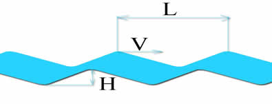
A wave of wavelength L (crest to crest) and height H (trough to crest), moving at speed V.
The energy contained in a wave is E = (1/8) × ρ × 9.81 × H² × L, with ρ the density of water in kg/m³ and H and L in meters, for each meter of crest width. It lets us estimate the energy absorbed by observed waves.
The waves created by the ship travel at its speed. Putting the boat speed in place of V in the previous relation gives the distance L between two crests of the waves it produces. If we then replace L by the waterline length Lf, Froude derives the number that measures the effect of waves on resistance: the Froude number, Fn = V / √(9.81 × Lf), with V the boat speed in m/s and Lf the waterline length in m. It tells us about the shape of the waves that accompany the ship.
The next figure shows the wave regime and the specific resistance Rh/Δ against Fn, for several ship types. Δ is the displacement, that is 9.81 × density × immersed volume, in newtons.
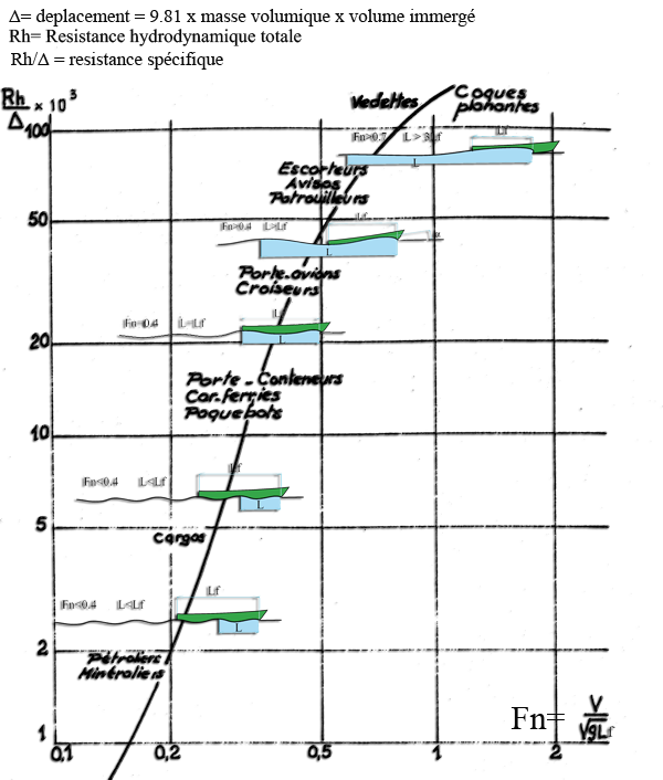
Specific resistance Rh/Δ against Fn. The faster and lighter the ship, the higher Rh/Δ: from tankers (low Fn) to planing hulls (Fn above 0.7, L > 3 Lf). The figure labels are in French ("Résistance spécifique" is specific resistance).
3: Wave resistance of a boat according to speed (Fn)
Fn below 0.4. The wavelength L stays shorter than the waterline length Lf.
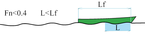
Fn < 0.4: several crests run along the hull, the wavelength L is shorter than Lf.
At low Froude numbers, below 0.26, at least three low crests run along the boat. Wave resistance is small, and friction accounts for 70 to 90% of the resistance to forward motion (values from the author of the source document). Above 0.26, wave resistance increases, and the interaction between the bow wave and the stern wave plays a significant role. It adds to or subtracts from the crest height. Let us look at it closely.
The ship generates two wave trains: the bow waves, which start at the bow, and the stern waves, created by the suction of water at the stern, which start at the stern and begin with a trough. Since the energy of a wave grows with the square of its height, wave resistance is stronger the deeper the troughs in the wave system. When waves add up, resistance rises; when they cancel, it drops. It therefore shows peaks and dips.
- If Lf is a whole multiple of L, a crest of the bow wave overlaps the trough of the system born at the stern and cancels it. Resistance goes through a minimum.
- If Lf is an odd multiple of L/2 (Lf = L/2, or Lf = 3 × L/2), the bow wave has a trough at the stern of the ship, which adds to the stern wave. Resistance goes through a maximum.
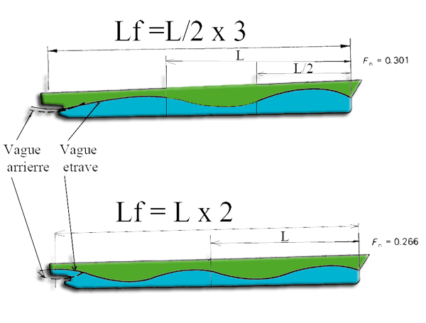
Two interaction cases: Lf = 3 × L/2 (Fn = 0.301, maximum resistance) and Lf = 2 × L (Fn = 0.266, minimum resistance). Figure labels in French: "vague d'étrave" is bow wave, "vague arrière" stern wave.
These remarkable cases correspond to a series of Froude numbers, which the next two figures place on the shape of the wave and on the wave resistance curve. They come from the author's source document: the simple relation of the previous section would give nearby values (Fn of 0.28 for Lf = 2 L and 0.33 for Lf = 3 L/2), but not identical ones.
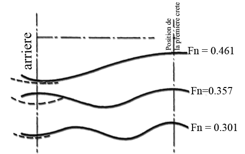
The wave profile along the hull for Fn = 0.301, 0.357 and 0.461, with the position of the first crest marked on the right ("arrière" is stern).
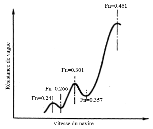
Wave resistance against speed: humps at Fn = 0.241, 0.301 and 0.461, dips at 0.266 and 0.357.
Fn equal to 0.4. The wavelength equals the length of the hull, and the stern wave is cancelled by the bow wave. This is the theoretical limit speed for which the hull was drawn. The ship sails in its own wave: a crest at the bow, a crest at the stern, the trough in the middle. Beyond it, wave resistance increases sharply.
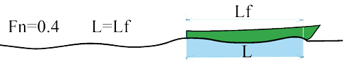
Fn = 0.4: L = Lf, a crest at each end and a trough in the middle.
Fn between 0.4 and 0.5. The ship climbs onto its bow crest, while the trough moves toward the stern. The hull tips, and an angle α appears. This is the most unfavorable situation. According to the author, wave resistance can reach 85% of the total resistance there, and the curve shoots up to a maximum around Fn = 0.461. The angle also increases the frontal area of the ship.
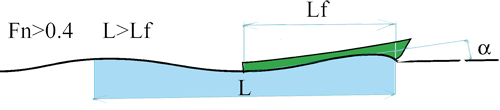
Fn > 0.4: the hull climbs onto its bow crest and takes an angle α.
Fn above 0.5. The ship sits on the crest of the bow wave and lifts its bow, returning to a horizontal position. This is the domain of the planing hulls of light vessels. A flat surface at the stern rests on the wave without sinking into it, keeping as much of the hull as possible out of the water. Wave resistance drops sharply. True planing begins around Fn = 0.7, when the wavelength exceeds three times Lf.
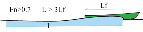
Fn > 0.7: the hull planes on its wave, L > 3 Lf.
4: How to calculate the resistance of a hull with Heliciel
Consider a calm, infinite body of water, with no aerodynamic resistance. The overall method follows these steps:
- calculation of the wetted surface;
- calculation of the displacement of the ship;
- calculation of the Froude number;
- estimation of the wave regime;
- estimation of the trim angle of the ship;
- estimation of the residuary drag by the Savitsky method;
- calculation of the viscous resistance, that is friction and pressure (form) resistance.
The Ship waves (Michell / Kelvin) window, opened from the Edit/Tools > Hydrodynamics menu, is the only hull resistance window. Heliciel computes the wave field and the wave resistance there with Michell's theory. Its Drag tab then gives the total resistance, with the method chosen by ship type: generic ITTC, Holtrop & Mennen for a displacement hull, Savitsky for a planing hull. The hull is loaded from a file, or declared from a data sheet.
To go further, we can follow the tutorial Ship waves and hull drag, study the performance of a hull, or see how the resulting thrust sizes a boat propeller.
 Global site map
 Mecaflux
 Tutorials Mecaflux Pro3D
 Tutorials Heliciel
 Tutorials Heliciel PRO CFD
 Mecaflux Store
 Compare software functions
 Quotes, Orders, Payment Methods
 project technical studies