
Pitch variation in heliciel
Design 3D models for propellers, turbines, tidal, wind, kaplan, foil, wings with heliciel software:
wind turbine blade propellers and wings 3D models
How to generate propellers turbine or wings 3D models with Heliciel propellers design software:
Heliciel generates 3D blade propeller airplane boat wind turbine fans. The 3D formats produced by Heliciel (IGES + STL) allows the construction of the blades with CNC or prototyping machines (eg stereolithography). the 3D IGES propellers export models, optimize surface states and allow the realization of prototype blades of high quality.
Here is a detailed list of the 3D functions of HELICIEL| 3D engine propeller héliciel | export to 3D format X | Export to SolidWorks | IGS and stl export formats |
Héliciel has its own animated 3D engine lets you view your project in three dimensions and movement.
Aside from the fact that it is nice, the ergonomic interest is real. The concept of elements, of the blade or wing, and profiles is highlighted. The selection of individual blade elements, onto the 3D model of the propeller, allows the user to view the settings for each element. The design of the base profiles and tip of each selected element, Appears beside the window to bring pitch information, and angle of fluid..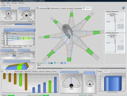
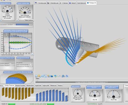
moving particles around propellers 3D model
A simulation of a variable blade pitch is accessible directly from the 3D model interface:
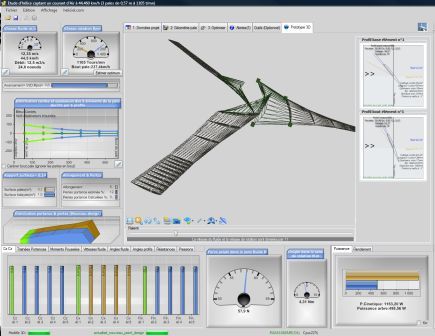
The user can select a texture of the blade which best represents the project.
2 Propeller blade export formats .STL and . IGES ( Initial Graphics Exchange Specification 5.3)Heliciel export blade geometry to .stl and . igs Format. Entities igs produced are 126 and 128 (spline surfaces and splines). The iges format is the most perfect 3d format to generate twisted surfaces for 3D propellers blade models. IGES and STL are recognized by all good CAD systems, by stereolithography machines or other prototyping machines.
Example of export IGS blade spline surface on a CAD system that can read IGS spline area:
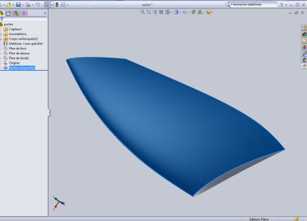
Propeller blade export to SolidWorks
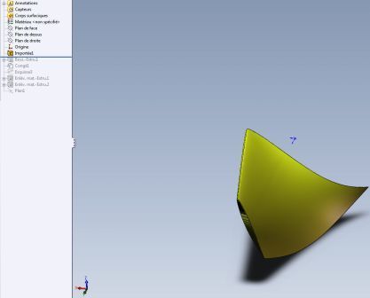
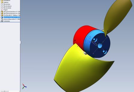
For users of SolidWorks CAD software, here is an example of creating of the blade of propeller with solidworks (same as Fusion 360):Use / file and export your blade to IGS format Open igs file with solidworks menu:
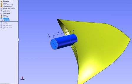
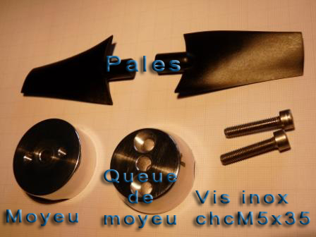
For ease of handling and assembly, displaying the origins in the parameter display solidworksHELICIEL.com produced and directed prototype blades and uses a type of adjustable hub (patented) that we use here . To connect the blade to a hub-type "heliciel" in an assemblywe will create a cylindrical part by extruding a circle from the top plan,up to the imported form of our blade, which will serve as an interface connection between the blade and the hub:
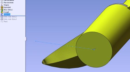
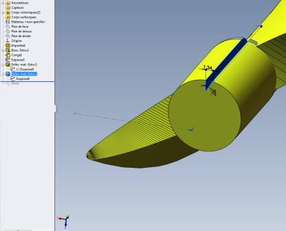
we put a notch coincident with the plane of rotation to allow adjustment of the setting. (The plane of rotation of the propeller is defined by the axis of y and z)
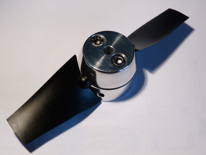
Here is an example prototype built by HELICIEL: :
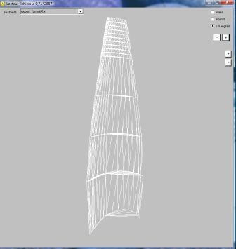
Export blade propeller format directx. X
The. X is the standard 3D format DirectX.The blade can be exported in this format from the File / Export / Format menu ".X". Player file. X is integrated héliciel and allows you to check the result of the export of your propeller or wing blade Format. X
 Global site map
 Mecaflux
 Tutorials Mecaflux Pro3D
 Tutorials Heliciel
 Mecaflux Store
 Quotes, Orders, Payment Methods
 project technical studies