
see also: evolution propeller design methods
Design: propeller turbine, screw, aerial, marine, turbine, tidal, wind, kaplan, foil, wings, 3D. Discover heliciel software: Modeling aerial propeller in heliciel Modeling a wing mast sail in heliciel Wings or foils modeling in helicielUnderstand and know the history of the aircraft propeller:
Nothing like That a brief history of the evolution of aircraft propellers, (1920-present) to quickly integrate the state of the art and understand how we got there.
- You can also visit the page for the history of the propeller general
This part of history of the aircraft propeller includes extensive excerpts from the book of John Grampaix "Propellers" cited in the bibliography of the site.
The technique of air propeller 1920
Before and during the war 1914-1918, the technique of the propeller is fixed universally: laminated wood sheets,shape obtained first by hand, Then the Duplicator in some propeller manufacturers. The propeller is varnished or lacquered.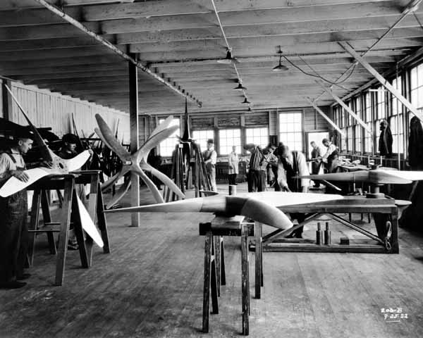
Profile: half the radius, the relative thicknesses range from 10 to 30%; widths of blades: 9 to 11 % of the diameter. Underside flat in the working party ; constant pitch throughout the blade, or increasing from the hub to the blade tip. A development occurs affecting profiles: to improve the lift/drag ratio- and increase performance - some manufacturers of propellers, realize thrusters with symmetric profiles. But they are quickly abandoned because they introduce a gap too big between the rotational speed, in level flight, and the rotational speed of climbing.
The manufacture of the propeller proceeds as much of sleight of hand, than technical ; It was as this , until the appearance of metal propellers.The propellers of this time, equip engines of fifty hp ; have a diameter of 2 m to 2.50 m and rotate at 1,200 rpm.. This gives at the blade tip, a tip speed of less than 150 meters per second. Given these low speeds, propellers resist easily, although based on summary calculations and imprecise techniques. Pas de problème d'adaptation non plus :No problem of adaptation either: aircraft having only a small amount of power, maximum speed in level is not much higher than the speed along the path uphill. So that the feed per revolution varies little, it keeps almost the maximum performance when climbing.The wooden propeller will progress, more in its manufacture, than in its aerodynamic quality and already, between 1920 and 1925, it will be insufficient for the new engines. It then turns to the metal propeller and we'll see it appear successively in two forms: the twisted board, cut profile..
1920 to 1940
During this period the aircraft performance is increasing largely And for propeller this results two levels of difficulty:- the peripheral speed at the blade tip approaching 300 meters per second (it was half the previous time). So that the resistance factors are multiplied by 4.
- aircraft having a larger excess power, the gap widened between the maximum cruising speed and the speed on the climb path. therefore, a serious problem of adaptation, as it happens, uphill, you lose up to 25% of peak performance.
- availability of finer profiles:
- significantly better performancer; higher unit strength of the metal, which can (thin blades) rotate at much higher peripheral speeds. At the time when the metal was introduced, the peripheral speed was a problem of material strength and not an aerodynamic problems arising from sonic speeds.
- More homogeneous material: strength arising from this homogeneity, better balance..
- ease of manufacture, repair.
- no deformation under the influence of time, storage indefinitely.
- Possibility to build propellers separate blades, it can not be considered to assemble a wooden blade in a metal sleeve..
- better aerodynamic performance of the hub, which does not require the extra thicknesses required by wood..
propeller "plate" twisted
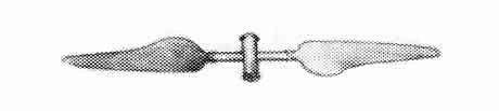
This is the American Reed, who filed the first patent metallic propeller (March 1921). Immediately after endurance test bench 30 hours, and the first test flight August 30, 1921.It was metal "planks" twisted relative uniform thickness - of the order of 5% - the entire radius of the blade (Fig. 37).Reed asked his blades to achieve by their flexibility, a partial balance between aerodynamic and centrifugal couples couples. In other words, the rigidity of the blades should be ensured by the centrifugal force rather than by their own strength. The idea was to "pass through" the bending forces. Concept that can be found today for helicopter rotors. he was achieved some balancing, but flexible blade had two serious drawbacks : blades "held" poorly the effort was asked to climb, they were too distorted and the rotational speed decreased. Moreover, too large torsional deformation of the blades caused efforts, which led to the ovalizations of mounting holes. These propellers were introduced in Europe by Pierre Levasseur - 1924 - which, first, built them under license Reed. They were of one piece, machined from a blank forged duralumin.They were extensively used until about 1930 and allowed Bonnet to fly more than 400 km/h in a Bernard-Hispano.
(fig. 37).
propellers carved out profile
After the era of flat metal twisted propeller blades , It was the one of the propeller carved out profile, stage we are still. Special case of the hollow blades, of soft sheet steel, welded to the torch.In 1930, this type was already exceptionally (Leitner propellers), but with sufficient flexural strength, he was accused of poorly stick to centrifugal forces, causing them to slip weld lines. From the beginning of the propellers carved, it was proposed to use two light metals, duralumin and magnesium. This is the first was retained; magnesium was blamed its low elastic limit (hence permanent deformation) and it was also involved, the difficulty of obtaining a magnesium always homogeneous. The general layout of the propeller appeared in 1930 as:- maximum width of the blade located at half the radius and around 8% of the diameter;;
- blade tip, tapered, thin (onset of compressibility at the blade tip, it approaching the speed of sound). The reduction in the width of the blade began to semi-diameter and it was very fast, which gave an extremity blade, very slender and therefore a relatively low centrifugal force.
- Thickness relative to the half-radius of not more than 6%.
propeller junkers cheeks
3 blade propellers :
The propeller of these decades, in general, two-bladed, but appear first three bladed. Maneuverability of aircraft has increased, they are thinner, faster, this increased yaw velocity, combined with the speed of rotation of the blades gives rise to gyroscopic effects, the analysis reveals that there would do well to get three blades instead of two: With three blades,vibrations caused by the gyroscopic effects disappear, especially harmful vibrations, that the aircraft are equipped with reducers.Indeed, the two-blade propeller has a moment of inertia null when it is in the horizontal position, and a maximum moment of inertia when vertical, while, in the three-bladed, the moment of inertia is constant.In the rotation of the two-bladed, each revolution, the gyroscopic torque through two zero values, and two maximum values ; while the torque is constant for the three-bladed. The interest of bladed propellers is quite obvious because, besides the benefits just mentioned, we have to fear no increase in weight: a three-bladed well drawn is equal weight, sometimes less, than its two bladed counterpart. Finally, when they began to worry about issues of compressibility for the propeller at the blade tip, the three bladed type allowed, a reduction in the diameter - thus in the peripheral speed of the order of-7 %. From about 1930, there was concern about compressibility effects on the blade tip when the tip speed was the order of the speed of sound.By this time had been registered a sharp drop in performance when was in such critical conditions. And it was found that the effects of compressibility were mitigated by the use of very thin profiles, and very close to sharp leading edge. At the extremities of the blades, the front area of the profiles to be found around the half-chord: In short, the characteristics that we find today in the wings of supersonic aircraft. The experience of the propeller was used for aircraft manufacturers, when they were dealing with very high speeds. To the different points of view mentioned above, the four-bladed brought the same improvements as the three bladed ;However, it was a lower efficiency because it was reduced by the interaction of the blades..Growth and limits of the relative pitch:
The gradual improvement of the maximum propeller efficiency, from the beginnings of aviation to 1930, corresponds to a continuous increase in the relative pitch:the relative pitch increased from 0.4 to 1.2. ll reaches 1.4 only for aircraft speed record,where the power per square meter of area swept by the blades exceeds 350 hp. Beyond, for the same peripheral speed, the maximum efficiency decreases as the relative pitch increases.The relative pitch is the ratio of the propeller pitch to the diameter. In a high relative pitch, so there is a large angle of incidence between the blade and the plane of rotation.Beyond these numbers, expressing the pitch relative performance tends to decrease when the peripheral speed increases.The performance curves, depending on the feed per revolution, spreading less, thus indicating that the adaptation of propellers is less flexible. The propeller, corresponding to a compromise, takeoff and climb suffer from this less adaptability. These curves show that for the same speed, peripheral tractive effort per square meter of swept area of the propeller begins to decrease when the relative pitch approach 1.8.
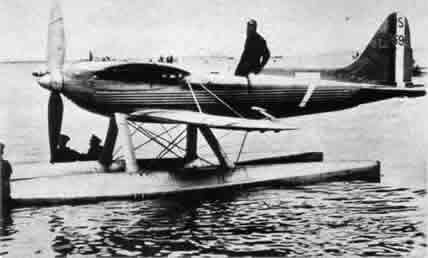
A parenthesis to cite a particular case, that of the Schneider Trophy seaplane.These aircraft were equipped with propellers that were characterized by a great relative pitch; Moreover, almost the entire surface the propeller participated in the work of propulsion:
Which solution to use to improve the performance of the propeller, so those of aircraft?
The gear is widespread on aircraft of this time, and increasing the relative pitch of the propeller, because it allows larger diameters an allow to reduces the speed.He spreads out the curve of his performance based on the feed per revolution, But we do not think the gear provides a solution, far beyond the usual relative pitch. And it is accepted that the only solution is the automatic adjustment of the pitch, following in a continuous manner, changes in speed. The variable pitch propeller is close
Parameters of the propeller I920-1940
It is obvious that the evolution into propeller and motor - and even that of the cell - were made in parallel. So that, in recent years in the technical literature, has emerged the initial GMP (Group Moto propeller) wishing thereby mean that the propeller engine, engine accessories, gearbox, compressor, the system pitch variation were a related set.We must therefore consider here the reducer, compressor, pitch variation whose implementation overlaps two decades 1920-1930 and 1930- 1940.propeller reducer :
The "reducer" existed on a large number of aircraft of the early ages of aviation; it was simply consists of two gears connected by a chain drive and was asked to increase the maximum performance by increasing speed of rotation of the propeller, due to the low speed of aircraft at the time. In fact so there was not a reduction but, instead, a system to increase the speed of rotation of the propeller (which explains the quotes added the word reducer).
When the aircraft speed increased, the "reducer" was dropped, and for many years, the propellers were mounted in direct contact, aircraft speed being sufficient to give a good peak performance under such conditions. For several years, we resigned ourselves to use motors turning 1 .500-1 .800 rpm: these engines had a considerable weight per hp, but we knew that this speed of 1 500-1 .800 rpm was the one that would provide a good performance of the propeller and were sacrificed everything to this efficiency (the propeller was obviously mounted directly on the motor shaft).But the speed of the aircraft continued to increase, and for exactly the opposite reason, that which had been adopted at the beginning of aviation was again mounted reducers - reducers real - about 1930, to reconcile high engine speeds, with sufficiently slow regimes into propeller. Was attributed several advantages to reducer :
- limiting speed, so can use larger diameters without fear the effects of compressibility.
- increase in the relative pitch of the propeller, thereby spreading the efficiency curve as a function of feed per revolution : hence proper performance rise and maximum performance in level flight. A high relative pitch is a big angle between the chord and the plane of rotation.
- increase the bollard pull, hence easier to launch aircraft high wing loading and seaplanes, whose planing is always difficult
- Increasing the diameter of propeller resulting in the following possibilities : from 7 - 8 it was in the year 1920 ,lift/drag ratio of aircraft was about 12 about 1930,while the aerodynamic braking, and high lift, were still very rare mechanical curiosities.It was interesting to have, downhill brake consists of a large propeller working in receiving: speed on the track - so landing speed - was thus reduced. And it was also of great interest to be able to brake after a long dive, by the rapid reversal of pitch of the propeller - what is possible today. However, it should be noted that this improvement had counterpart: the gear we have seen, increases the relative pitch, so that the propeller rotates slower in receiving ; as a result, the braking effect per unit area, of the swept circle is decreased. So by the use of reducer : on the one hand, improvement, on the other hand decrease of the braking effect of the propeller, This report ultimately is revealed beneficial. In other words the use of reducer improves braking by the propeller.
More generally, increasing the efficiency of the propeller, it is the overall performance of the aircraft, that the reducer improved, often in very large proportions : horizontal speed, ceiling, range of action especially... The various improvements, they then asked, to variable pitch.Gear and variable pitch are converging elements of the same problem: the propeller efficiency.
the compressor :
On an aircraft equipped with a compressor motor, the speed of rotation and translational level (for a constant-torque motor and a fixed pitch propeller), both grow at a rate of 5 % per 1.000 m. We thus see that the propeller will work very poorly on the ground and climb, if it is drawn to an altitude of recovery in the order of 6.000 or 7.000 m. With turbocharged engines, that is to say, with engines that keep their power at high altitude despite the decrease in air density, we fall back in the case of take-off : great speed deviation of the aircraft. It will be given a great pitch, to the propeller must work at high altitude, in a fluid of least resistance, but this pitch will be too big for takeoff.With the engine without compressor, that is to say, with the engine power decreases at the same time as the air density (and hence the resistance to rotation of the blades) can, if need be, to satisfied of a fixed pitch propeller, since the pressure ratio is very close to the ratio of the densities. The propeller is set for maximum performance at altitude use, and we made the sacrifice of the characteristics of takeoff and climb. With the engine without compressor, aircraft not exceeding 4 ou 5.000 m en vol normal,in normal flight, the performance gain would have provided the variable pitch propeller would not have exceeded 15 %. we were doing the sacrifice of these 15% since, in return, we did not have to worry about the complex mechanism of the variable pitch.But in the case of the supercharged engine, the engine power at altitude is equivalent to what it was on the ground ; so the engine at altitude, provides to the propeller the same power than on the ground,but this propeller in altitude, works in a rarefied air that does not oppose it the same resistance than on the groundl. the propeller will speed up and imposed on the motor, a rotational speed which is incompatible with the mechanical strength of it.. Solution: provide the engine with a device that maintains constant its speed of rotation, and therefore that of the propeller. But then this propeller will no longer reject sufficient air mass flow is decreased, the desired propulsive effect - which is a function of the flow - will also be reduced.Of this review, so it appears that the engine compressor can be conceived only if activates a variable pitch propeller. Continuous duty motor and variable pitch propeller are inseparable.
In the 1920s, the variable pitch propeller appeared as a necessity, but the question was complicated when he had to go to the design, with engines of 100 or 150 hp. the centrifugal force is not huge, you could make the arms of the blades rotate in smooth metal sleeves without the friction due to centrifugal force are too high. But with the 300 hp engine. this centrifugal force already reached twenty tons, hence considerable friction, which have forced make use of special steels and led to larger hubs..
We could afford to leave in boxes, the problem of variable pitch propeller for some years after 1920 ; but we had to find solutions when appeared the devices to restore power at altitude, as the turbocharger Rateau, which allowed to increase the ceiling planes, and their speed to high altitudes. Technicians have tackled the problem with various optical -will be seen later -. It was even discussed the problem of variable diameter propeller (who has never received a viable solution) by performing the following tests which the blades, obeying the pilot action,must be screwed or unscrewed on a mandrel,increasing and decreasing alternately, the "useful" diameter. of the propeller.
The variable pitch propeller, deserves a page to itself: a variable pitch propeller
 Global site map
 Mecaflux
 Tutorials Mecaflux Pro3D
 Tutorials Heliciel
 Mecaflux Store
 Quotes, Orders, Payment Methods
 project technical studies