
Aircraft propeller simulation in heliciel software
The aircraft propeller design and evolutions
- See also: Tutorial build aircraft propeller
- You can also refer to: a brief history of the evolution of aircraft propellers (1920 to 1940) to quickly integrate the state of the art and understand the source of the modern propeller.
Understand and master the aircraft propellers design and evolutions:
After 1940 the propeller must be closely monitored because some of the current and future developments can be inspired by what has been done. In addition, the propellers parameters (blades length, width, number), were pushed to their limits, it's interesting to know these limits by studying this part of the history of the propeller if you want push them back. This article draws extensive extracts from the book of John Grampaix cited in the bibliography of this site....Speeds and power planes have not stopped growing in previous years. How did the propeller "absorbed" the new parameters? The increase in speed has helped the propeller, allowing large relatives pitch: they reach 1.7 and 1.9 even without being prohibitive, nor the diameter, nor the rotational speed. In particular the relative pitch of 1.9 is specifically retained in commercial aviation, where the care is first, to economy in cruise..The propeller is not at the top of its ability : a further increase in aircraft speed is easily followed by a corresponding increase in rotational speeds- Where will follow a reduced diameter propeller, therefore the weight of propellant and corollary, weight reduction of the motor and process of landing. But already, it s' guides to the profiles knife for blade tips, to answer to the effects of compressibility. The increased powers, posed a difficult problem to the propeller :the mass of the propeller increases with the corresponding engine power, but the increased mass of the propeller is faster than the increase in power and engine ground. The propeller would find it there, its limit ?
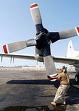
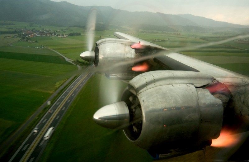 engine Super Constellation takeoff
Several solutions were considered :
- regulating the engine torque, to reduce the periodic forces that the propeller must absorb.
- increase the number of blades, allowed by large relative pitch ;it is evident that more than the pitch of the propeller is large, Less air is disturbed in which each blade works, when it comes in the wake of the previous blade. Therefore, the loss of performance that comes from largest number of blades is compensated by the large relative pitch.
- fractionation of the total power of the plane in a larger number of engines..
- use of contra-rotating propellers
Over the years that saw the construction of large four-engine - « Super-Constellation », DC-7, « Superfortresses », Boeing -propellers obviously had to adapt to the new performance - speed and power allowed by the engine that equipped these aircraft. It is piston engines of 3,500 hp., power where the alternative system has found its term..
propeller Super Constellation
Then came the turboprop, even higher performance, of different operating characteristics. And it was a new range of adaptation of the propellers. To accommodate the new powers, manufacturers of propellers, played on these parameters:
- diameters
- Lengths of blades
- Forms (in plan profile)
- the number of blades
- the number of propellers on the same shaft (contra-rotating system)
- the speed of rotation.
The general pattern of adaptation of the propellant, is the following :
- when the engine power increases - for a given propeller- one can, for example, increasing the angle of attack of the blades, or increasing the surface, by varying the width of the blade, or diameter. But we are limited in this way : due to one or the other of these changes, performance decreases, and the powers required to change pitch, become prohibitive.
- One can also choose another solution to absorb the increase in power:for example-and it is a variant of the increased surface-one can increase the number of blades. But we see the limitations: interaction between the blades, "thickening" of the hub. This leads to similar compromise when necessary to increase the speed or altitude aircraft.
the diameters :
Higher speeds were not so much to scare propeller designers, who had met with the transonic in 30-35 years with propellants that equipped seaplanes of Schneider Cup. Specialists had established at the time that the ends of blades endured well transonic , Provided they were very thinned and a sharp leading edge. The results gave their reason as they demonstrate Ratier propeller turning at 345 meters per second blade tip with a yield of 82%. Still, this is no longer just the tip of the blade, but the entire propeller was likely to be supersonic ; the propellant had to be returned at the construction site.
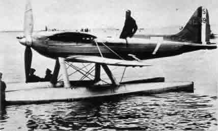
Schneider Cup seaplaneA diagram gave some reassurances;he showed variations of the drag coefficient of a profile between 900 and 1 .600 km / h .It appeared that, apart from a "point" between 1110 and 1300 km / h , propeller would accommodate pretty much the supersonic.The diameter evolved between these two terms:
- long and narrow blade, very tapered tip, so that the poor performance in supersonic applies to a small area - the very tapered tip.
- short and wide blade with square tip, so that the blade tip - who was asked a similar work to that of other sections -not moving in very high speeds.
At the onset of the great powers, he was tempting to increase the width of the blades, we easily passed from 7 to 8% of the length of the blade at about 10%. But going further, designers propellers were facing two levels of difficulty:
- separations boundary layer may occur.However, it can be remedied this problem by the use of hollow blades making the suction of the boundary layer, the centrifugal force helping this aspiration.
- excessive width of the blade requires too high to ensure the pitch variation power.
The same motor can receive various kinds of propellers, able to absorb its power. But very different one from the other ,depending on whether the user wants to focus on takeoff, the cruise speed, the economy. As it wants to get a particular compromise between the various parameters.To adapt a propellant that suits him, to this engine - which corresponds to the chosen objectives - So we play on the plan shape of the blades, their profile, diameter, width. To deal with new requirements, 70 years ago, various forms of blades appeared that were , from scimitar, to the square tip blade ,the first by aerodynamic analogy to the swept wing. The "square tip" imposed itself. Designed around 1946 by Hamilton Standard,This propeller type is also characterized by its profile : it is processed in laminar profile,-that is to say, its frontal is deferred to the back and the leading edge is very thin - it is the propeller of which we speak a few lines below.
When the sonic speed at the blade tip appeared, propellers designers thinning ant tapering the profilesWhen the speed of the aircraft increased (the total blade tip speed is the product of the circumferential speed and the translational speed of the airplane) this remedy has been insufficient. To cope, Hamilton released a propeller, however, was wide and at right angles at the tip of the blades: in contrast with the previous design, the blade tip is part of the active surface of the propeller, but the diameter of this propeller is reduced,which lowers the circumferential velocity and therefore "out" the marginal edge of the blade of the sonic area, as we have seen about the change in diameter. To solve the same problem, Curtiss employed another method :the wings strongly arrow giving the best results at very high speeds, why not implement this design in the field of the propeller? This was done and gave scimitar propeller. Forms more singular blades have been tried, but ultimately it is the propeller square tips that is imposed for high speeds.
- D.C.3 the propeller, 3 m. in diameter, weighs 170 kg and absorbs 1,200 hp.
- D.C.6 the propeller, of 4 m. in diameter, weighs 175 kg, absorbs 2400 c. and travels a pitch variation sector three times greater..
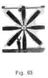
And that progress can be measured also with the dimensions of a propeller made in the United States : CurtissWright has operated a propeller "Octoprop"(fig 63 ) for a turboprop 15.000 ch (is the total power of a «SuperConstellation») two counter-rotating four-bladed of 5 m. 79 diameter, setting flag, reversibility; Hollow blade steel. This is the largest propeller ever made. it remained at the prototype stage. The largest mass-produced propeller is that of B-36 : it has the same dimensions as « Octoprop », but is not mounted counter-rotating.Profiles :
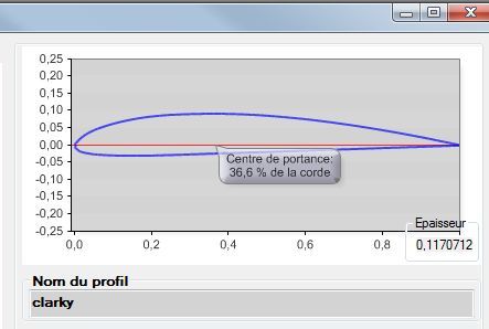
relative thicknesses of 5 to 5.5% for speeds of 700-800 km/h. and 4,5 % for 900 km/h.Variable curvature
In the period 1920-1940, we examined the concepts to increase the efficiency of the propeller. It appeared that, in terms of achievements, one could be implemented, the pitch variation.But among the concepts there was that of the variable curvature and a realization of this order was born in Hamilton in 1960, research on VSTOL is not foreign to the case.Propellers tested with Hamilton, were doublets at constant speed, each having 3 or 4 blades. These consisted therefore in fact two propellers, each with its hub mounted one behind the other on the same shaft. In fact, we wanted to establish the propellant system with its wing flaps too ; but such a design relatively easy for the wing, is extraordinarily difficult for the propeller because of its high speed. Until while, all solutions with an additional structure on the propeller failed. Hamilton has approached the problem differently.
In the Hamilton system, the operation of each propeller is related to the other propeller the pitch of each of them varies according to a law that binds the two surfaces of the front propeller and the rear propeller. These differentially not vary, the variation of the one and the other is a function of the flight configuration : takeoff, climb, 'Cruise. Each pair of blades is therefore a unique aerodynamically slit surface ; therefore it is clear that varying the pitch of a blade is exactly equivalent to vary the curvature of the doublet, as it is for the wing and flap. With conventional propeller profile choices is a compromise between the requirements of takeoff, and those cruise flight. With the propeller Hamilton each pair of blades is somehow a profile specifically suited to each configuration.One phase to another, the operation is as follows :
- for takeoff and climb, each propeller blade front, is "small pitch position, the pitch of the rear propeller is greater. Each pair of blades is a unique profile of high curvature, good performance at low speeds.
- As the airspeed increases, the front blades are placed at a greater pitch :all works thus in large pitch (that of high speed) and the curvature is diminished, profile of each doublet becoming a high speed profile
- devices autonomy (aircraft anti submarine warfare, for example) : 20% increase
- transport aircraft Mach 0,7 - 0,8 increased autonomy 40 % ; increased payload 30 %.
- VSTOL : increased payload 50 %
- In general, decreased length tracks 15 %,.
The number of blades:The propeller Hamilton is not widespread. But it does not say that it will not appear on the turboprop, giving them a considerable boost.
Experience shows that the maximum number of blades on the same hub must not exceed ... 5,6,7 ..? If this number was higher, the hub excessively hypertrophied, require a cover that would lose the benefit of low frontal area permitted by turbine. Moreover, if the number of blades was higher, problems would arise:
- Interaction between the propeller blades
- Also problematic for the compressor supply
- Finally, increasing the number of blades, the rotational speed is reduced for a given power.
for more info about contrarotating, a tutorial design contra-rotating propeller héliciel is available.Final stage regarding the propeller, for adaptation to the big powers, the counter-rotating systems mounted the past few years on Bristol « Brabazon » , Saunders-Roé, « Princess » Tupolev-Tu-1 1 4
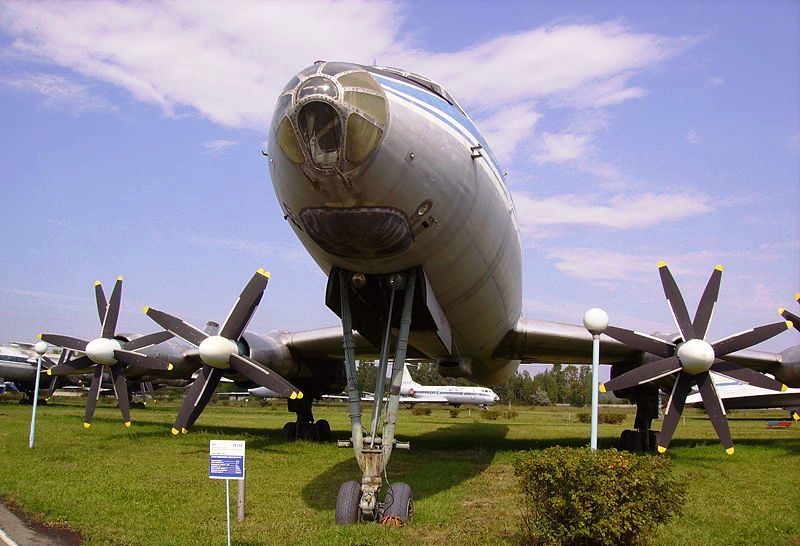 Tupolev-Tu-1 1 4
In the first case, the propellers are related to free turbines coupled ; in the second case, the propellers are driven by direct drive turbines,each propeller, in the latter case, is driven by its own turbine..Appliquées aux moteurs à pistons,Applied to piston engines, we must remember a realization of counter-rotating propellers : Ratier did install on the fighter V.B. 10 (2 Hispano-Suiza 12 Z of 1350 ch. each disposed in tandem) two co-axial 3 blade, pitch change of the rear propeller driven by a fixed electric motor ;turning electric motor control for Front Propeller. In some versions, the change of pitch was done by two fixed electric motors. The maximum system performance is achieved when the two propellers absorb equal torques ; to achieve this, we must give the rear propeller, a pitch slightly lower than the front propeller.
The advantage of the system:
- removal torque reversal, and gyroscopic torque, resulting in increased maneuverability..
- wake straightened, the energy lost in the rotation speed of the fluid is recovered by the second propeller
- smaller diameters
- best performance takeoff and climb especially heavy loads ;
- in the case of non-coupled propellers, not asymmetrical operation, in case of failure of one of two engines : A propeller is set flag, the other continues to run without much reduction in efficiency.
On the other side of the inevitable compromise, we must remember, against counter-rotating systems:
- towards instability caused by the effect of system drift. May compensate by increasing the area of the vertical stabilizer of the aircraft.
- greater complexity.
Here's a story about a spitfire with contra-propeller :
the vibrations
The propeller is subjected to vibration, whose sources are different :one is driven by the engine, one comes from the location of the propeller, others are specific to the propeller, and others from diverse backgrounds.
- engine. - Ttorsional oscillation very significant, are generated by the motor piston; Torsional vibration of the the crankshaft causes considerable alternating stresses in the hub and the propeller blades. They need strengthening the base sections of the propeller,compared to what they had been,to meet the conditions of the calculation of aerodynamic forces and centrifugal. To remedy this situation, may be interposed between the engine and the propeller, a flexible coupling, whose role is to reduce the effort, that originate in the hub due to the irregularity of the engine torque, and prohibit born regime resonance between the engine vibration and those of the propeller. In addition, the dampers are mounted on the crankshaft and engine are linked elastically to the cells. These vibrations - that arise from alternative system - does not occur in the turboprop. Therefore, with the turbines, it is possible to use thinner and lighter propeller.The specific weight of the propeller turbine is located around 70 - 80 gr. per horse for single propeller.
- Location of the propeller. This aerodynamic excitation results from the interaction between the propeller and the engine hood,, The leading edge of the wing, landing gear, basically anything that is an obstacle to the flow of the air mass brewed by the propeller. Hence the need to draw, taking into account the propeller, any part of the aircraft concerned by the aerodynamic field of the propeller. It may be necessary to also change the number of propeller blades, for influencing the frequency of the vibrations from the propeller. It should also take into account the mutual influence of propellers placed on the same wing and the propeller-ground interaction, which, caused ruptures of blades to Junkers.
- propeller. Specific propeller vibration come from :a static imbalance, the dynamic imbalance, an aerodynamic imbalance, an internal aerodynamic excitation:
- static imbalance. - Due to manufacturing imperfections, it is easily remedied by a simple operation control.
- dynamic imbalance. - This failure comes from the distribution uneven of the masses in the propeller. It may be detected only when the propeller is in motion. As a first approximation there remedied by performing static balancing to different pitch of the propeller. A rigorous solution requires very large installations ;Including a huge shell of steel, in two parts, between which there is an absolute vacuum into which turns the propeller testing. There is such equipment at Hamilton Standard.
- Aerodynamic imbalance.. - This imbalance is caused by small differences in shape or pitch, from manufacturing tolerances or adjustment that may exist between the blades of the same propeller.These blades provide unequal thrusts and absorb uneven couples. The equipment of current tests allow to detect such defects which can be remedied.
- Excitation internal aerodynamics. -It is a question here of vibrations that occur between the blades of a propeller ; they were found on the four-bladed propellers or more but not on 3 blade. They don 'cause any reaction on the propeller shaft.
- Vibrations of various origins. - These are the ones that occur in incidental cases : Aerodynamic excitation when passing an obstacle, in crossing a turbulent air layer, in the wake of any mobile.
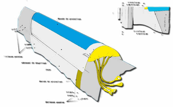
The leading edge of the propeller, as the wing is subject to icing. Pour l' en préserver, two "schools" defrosting and anti-icing.The anti-icing is permanent, the system to prevent icing, being put into operation as soon as the plane detects the danger of icing. While defrosting operates only after the formation of ice. For the anti-icing of propeller means tested contribute towards a common goal: supplying heat to the leading edge ; by electric current (typically) by circulation of hot gases inside of the blade in the case of hollow blades. For the defrosting, this is the chemical method that is used ;a pump delivers glycol in a ring fixed to the hub of the propeller, of this ring go fine tubes that lead to the root of the blades ; therefore it is the centrifugal force that does the rest, throwing glycol along the leading edge. The "rain"of glycol then causes the fall of the ice.
The propeller in our time is past the piston engine of 3,500 hp. to a range of turboprop power reached 7,500 hp (Pratt et Whitney T-34) ; what were the impact on the propeller ?Electric anti-icing
We must consider these elements : the pitch variation ; the reducer ;the compressor supply ; the three coupling propeller-turbine systems:Of course, as the piston engine,the variation of pitch covers an area which extends from small pitch, reversibility, through the large pitch and the feathering. But a pich still below small pitch is required to start,at least in the case of the direct-coupling propeller turbine. The piston engine can start a propeller to takeoff pitch, the direct drive turbine, has not enough power in static, the power curve lying below, of the curve of power absorbed by the propeller. The other two cases of coupling are similar to the binding propeller-piston engine for the "startup" phase.The pitch variations
The reducer turbine propeller is heavier and more complex than the gearbox piston engine-propeller. This is readily understood, the turbine rotating much faster than the engine crankshaft piston. However, based on the experience gained through the implementation of many gearboxes for aircraft reciprocating engines, manufacturing reducers turboprop is well developed..THE REDUCER
With the piston engine there was no major drawbacks to fix various accessories on the nose of the engine, it is otherwise with the turboprop :the compressor must be fed properly. Hence a reduction of the height of the base of the foot of blades, and the hub which contain them,miniaturization of accessories, new designs of covers.COMPRESSOR SUPPLY
THE THREE SYSTEMS COUPLING PROPELLER-TURBINE
The propeller can be coupled to the gas turbine following three formulas:
- Direct coupling: the turbine drives the compressor and the propeller.
- coupled by compressor compound -The first stage of the turbine drives the compressor free centrifugal. -The second stage, actuates the axial compressor and the propeller..
- coupled by free turbine. - The first two stages of the turbine drive the compressor. The third stage of the turbine drives the propeller
Even now, no supersonic propeller is in use ;the extreme case, today as yesterday, is that of the blade tip "touching" this area. In case of need to increase propeller speed. Doctrine, moreover, would be "all" or "nothing" : the entire blade in the supersonic, or none portion of the blade. Hence it follows that the profiles, while evolving, are still not revolutionary : we are at NACA - 16 which the frontal area is around 50 % the chord length ; when the leading edge, if it is refined, is not to the knife.Propeller SUPERSONIC
Sixty years ago, we have seen, the ends of blades, in very special cases (Schneider Cup) "brushed against" the supersonic . Since they did not go further in this Zone, various provisions - we have indicated - allow the propeller to avoid supersonic flows
However, as an experiment, it was made supersonic propeller, and we cite as an example, tests that go back a few years. These tests, carried out atLangley Field, were led by the NACA.They were led by a Mc Donnell XF - 88 B (derived from XF-88.A « Voodoo »)arranged in bench test flying. It was equipped with two reactors Westinghouse J-34 but,In addition, he received a turboprop Allison XT 38 who was operating the propeller testing, a Curtiss with 2,3 or 4 blade of diameter 3,05 m ; 2,15 m. ; 1,20 m. Aboard the plane, an electronic recording equipment. In fact, these tests, interested whole American technology,as collaborating with the NACA, the Laboratory of the propellers of 'USAF'. Air Development Center de Dayon (Ohio), l'us Navy Bureau of Aeronautics and Mc Donnell Saint-Louis
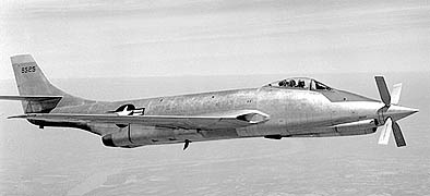
Mc Donnell XF - 88 B
 Global site map
 Mecaflux
 Tutorials Mecaflux Pro3D
 Tutorials Heliciel
 Mecaflux Store
 Quotes, Orders, Payment Methods
 project technical studies